The Correct Order for Motherboard Standoffs Installation
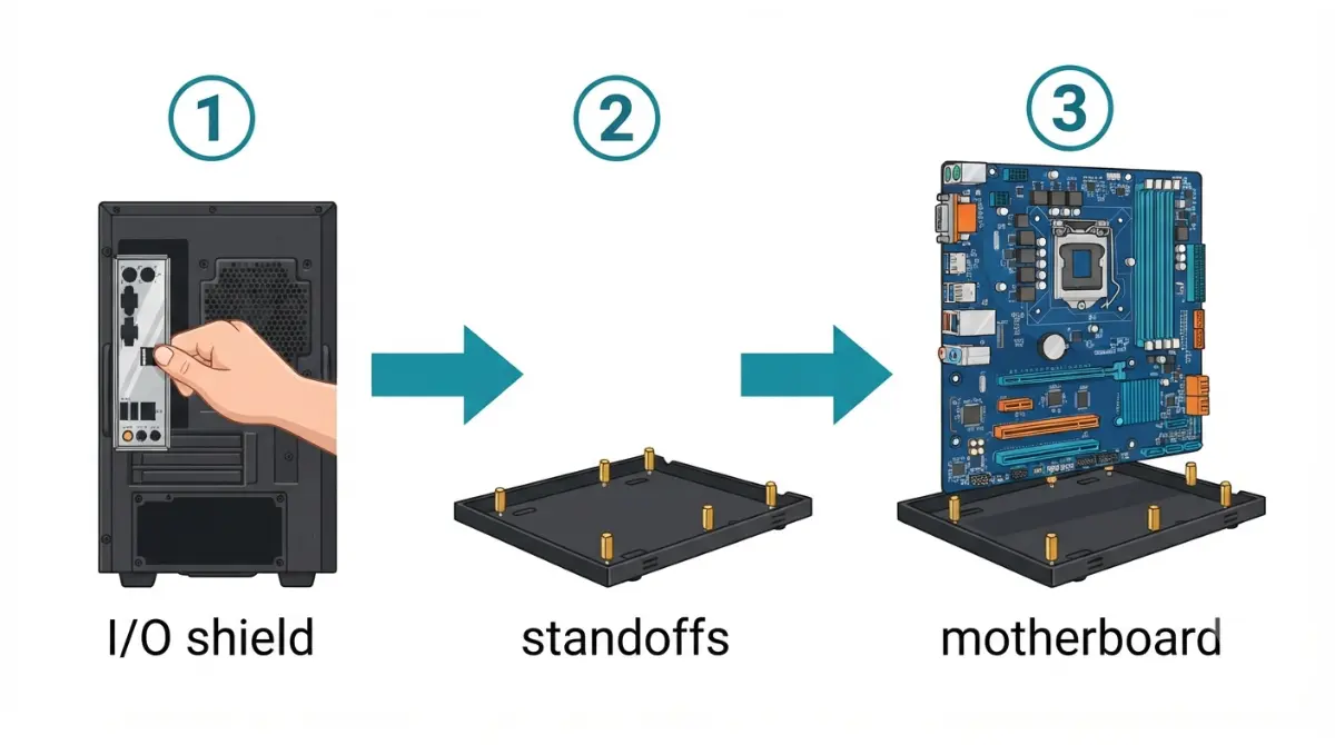
Table of Contents
What goes in first: standoffs, I/O shield or the board?
The motherboard always goes in last. If your board came with a separate I/O shield, that shield goes into the case first, as ASUS lays out in its own motherboard installation guidance. Next you confirm the motherboard standoffs, and only then do you lower the board.
The one-line answer
The order is shield, then standoffs, then board. Get it wrong and you’ll be unscrewing the whole board to fix it.
Which path are you on?
- Shield already attached to the board: skip the shield step and start at the standoff check.
- Shield loose in the motherboard box: fit it into the case before anything else.
- Board already in, but ports are blocked or holes don’t line up: jump to the troubleshooting section below.
What standoffs and the I/O shield actually do
Both parts sit between your motherboard and the metal case, and each does one job.
Standoffs: spacing and support
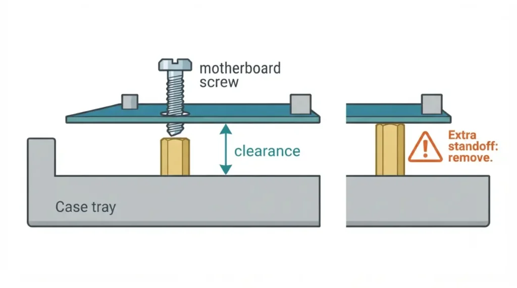
Standoffs are small threaded posts that screw into the case’s motherboard tray. They hold the board clear of the metal so the solder points on its underside never touch it. Each one also gives a mounting screw something to thread into.
The I/O shield: port frame and grounding tabs
The I/O shield is the thin metal plate that frames your board’s rear ports in the case opening. Many have small springy tabs on the inside that press against the ports. Some boards come with the shield attached at the factory, which is called an integrated I/O shield.
🔍 Why It Works: A standoff belongs only under a mounting hole, because that’s the only place the board is designed to touch it. A standoff anywhere else can press against the board’s underside and create an electrical path that shouldn’t exist.
Do your case’s standoffs match your motherboard’s holes?
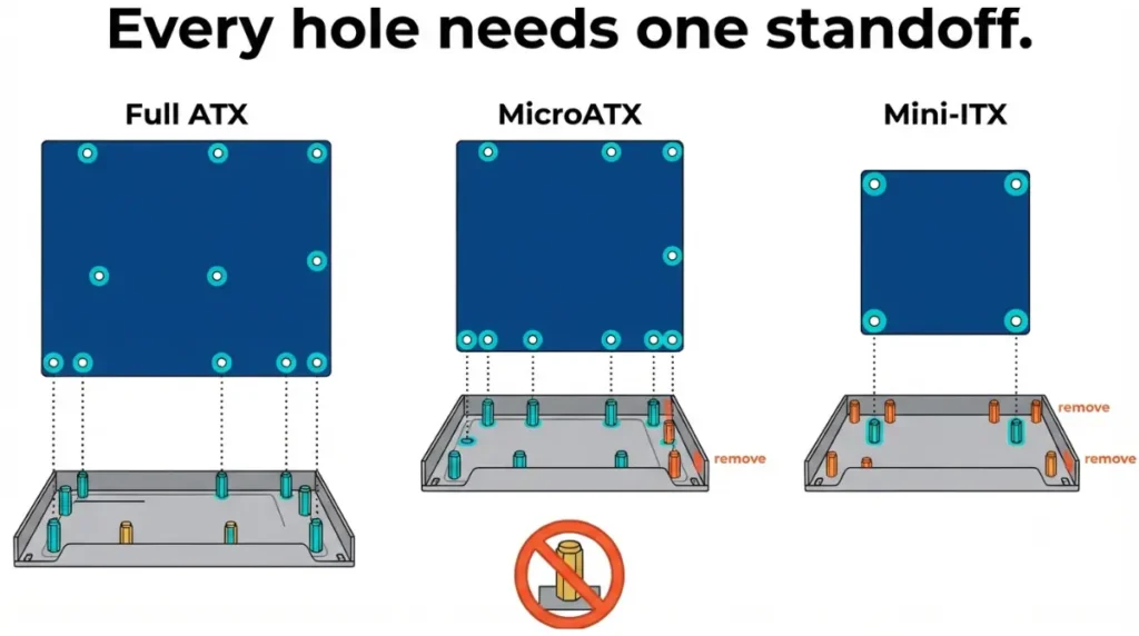
You need one standoff for every mounting hole on your motherboard, no more and no fewer. An extra one can short the board, and a missing one leaves part of it unsupported.
Count holes, then count standoffs
Open your motherboard manual’s layout diagram and count the mounting holes. Then compare it against your case manual’s tray diagram, or rest the board lightly over the tray, and confirm a standoff sits under each hole.
ATX, microATX and Mini-ITX hole positions
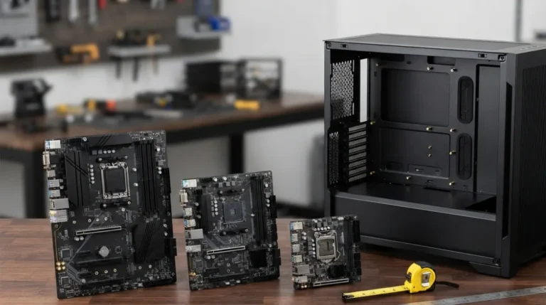
The microATX specification aligns its mounting holes with ATX positions where possible. That means a smaller board usually uses some, not all, of the positions an ATX case provides. A full-size ATX board measures 12 × 9.6 inches (305 × 244 mm) per the original ATX specification, which is why a case pre-fitted for ATX can leave extra standoffs under a smaller form factor.
Standoff–Hole Match Map
| Your board | Your case’s standoffs | What to do | Where to check |
|---|---|---|---|
| ATX | Pre-installed for ATX | Confirm each sits under a board hole; add any missing | Board manual layout + case manual tray diagram |
| microATX or Mini-ITX | Pre-installed for ATX | Remove every standoff with no hole above it | Board manual layout; tray markings if your case has them |
| Any size | None pre-installed | Install standoffs only where your board has holes | Case manual accessory list (count and thread type) |
| E-ATX or larger | ATX-sized tray | Confirm the case supports that board size first | Case spec page (supported form factors) |
Source: The Silicon Scroll decision map, built from the ATX and microATX specifications’ shared mounting positions and manufacturer installation guidance. No prices.
#6-32 vs M3: check your case manual
Standoffs and motherboard screws come in #6-32 and M3 threads, which look nearly identical but aren’t interchangeable. Use only the screws your case’s accessory list assigns to the motherboard. Hole alignment is one physical fit check among several, so it’s worth taking time to check full motherboard compatibility before you order, from socket to BIOS to lanes.
🧩 Compatibility Check: Find the mounting-hole diagram in your motherboard manual and the tray diagram in your case manual. If a pre-installed standoff has no matching hole, remove it before the board goes in.
The mounting order, step by step
These six steps follow the order board makers publish. Where your own manuals differ, follow them.
Before you start
Clear the case interior, lay the case on its side, and keep both manuals and the case’s screw bag within reach. Touch bare metal on the case before handling the board to discharge static.
Steps 1–6
- Fit the I/O shield from inside the case (separate shields only), with its cutouts matched to your board’s rear ports.
- Verify the standoffs against the Match Map above.
- Lower the board at a slight angle, rear ports first, into the shield opening.
- Align the holes over the standoffs and check that every port shows cleanly through the shield.
- Start each screw by hand so it threads straight.
- Tighten in a cross pattern until each screw is snug.
Case makers document this sequence too. Fractal Design’s standoff and I/O shield guide for its Core 1100 is one example, but your own case manual is the one that applies.
How tight is tight enough
Stop as soon as the screw seats firmly. The manufacturer guidance cited here gives no torque figure, and forcing a screw can strip the standoff’s threads or stress the board.
⚠️ Watch Out: If a screw resists within its first turn, it’s probably cross-threaded. Back it out completely and restart it straight, by hand.
Integrated vs separate I/O shield: what changes
Your shield type changes only the first step.
Pre-attached shield: skip a step
An integrated I/O shield installs with the motherboard itself. Start at the standoff check, then guide the board’s rear edge into the case opening.
Separate shield: which way it faces
Hold the loose shield against your board’s rear ports first so you know its orientation. Then press it in from inside the case, corner by corner, until it sits flush all the way around.
Open or unusual cases
Some open-frame or test-bench cases have no rear I/O opening. Follow that case’s manual on how, or whether, it uses a shield.
✅ Do This: Before lowering the board, check your motherboard box for a loose metal plate. If there isn’t one and none is attached to the rear ports, confirm with your board manual before continuing.
What to install on the board before it goes in
Some parts are far easier to fit with the board lying flat on its box than inside the case.
Usually before: CPU, RAM, M.2
The CPU socket, memory slots and M.2 slots are easiest to reach before mounting. If this is your first build, see how to install a CPU without bending pins. M.2 drives fasten to the motherboard with their own small screw or latch, separate from the case standoffs, and your board manual shows which one it uses.
Depends on your cooler and case
Many CPU coolers mount with a backplate behind the socket. If your case tray has no cutout there, that hardware may need to go on before the board is mounted. Height and RAM clearance are covered in the CPU cooler compatibility guide.
Board won’t line up, or ports are blocked? Check these
Most mounting problems trace back to the shield or a standoff, and each has a simple check.
Ports hidden behind shield tabs
If a USB or network port won’t accept a plug, an I/O shield tab has probably bent into the opening. Remove the board, fold the tab back out of the port’s path, and remount.
Screw holes don’t meet standoffs
Either a standoff is in the wrong position, or your board’s form factor doesn’t match the pre-installed layout. Recheck the Match Map.
Suspect a stray standoff
Don’t power on. Remove the board and recount the standoffs against your manual’s hole diagram.
⚠️ Watch Out: If the board was powered on with a standoff touching its underside and now won’t start, don’t attempt a repair. Contact your motherboard maker’s support and ask about warranty options.
Motherboard standoffs and I/O shield: quick answers
1. Does the I/O shield go in before the motherboard?
Yes. A separate I/O shield goes into the case opening before the motherboard, as ASUS’s installation guidance directs; integrated shields skip this step.
2. How many motherboard standoffs do I need?
You need exactly one standoff for each mounting hole on your motherboard. Count the holes in your board manual’s layout diagram, then match them.
3. Are motherboard standoffs pre-installed in cases?
Many cases ship with standoffs pre-installed for ATX boards. With a microATX or Mini-ITX board, remove any standoff without a hole above it.
4. Can I use M3 screws in #6-32 standoffs?
No. #6-32 and M3 motherboard standoff threads aren’t interchangeable, so use the screws your case manual’s accessory list assigns to the motherboard.
5. What happens if I install an extra standoff?
An extra standoff under a spot with no mounting hole can touch the board’s underside and cause a short. Remove it before powering on.
6. What is an integrated I/O shield?
An integrated I/O shield is attached to the motherboard at the factory, so it installs with the board and needs no separate case-fitting step.
7. Do I need to install the I/O shield?
If your motherboard includes a separate I/O shield, install it; the board maker’s instructions place it in the case before the motherboard goes in.
8. Should I install the CPU before mounting the motherboard?
Installing the CPU and RAM before mounting the motherboard is easier. Whether the cooler goes first depends on its backplate and your case’s tray cutout.
9. Why are my ports blocked by the I/O shield?
An I/O shield tab has likely bent into a port opening. Remove the motherboard, fold the tab back out of the way, then remount.
10. How tight should motherboard screws be?
Tighten motherboard screws in a cross pattern until they seat snugly, then stop; forcing them can strip threads or stress the board.
Mount it once, mount it right
Fit the shield first, match a standoff to every hole, and put the board in last. With the board secured, the next steps are wiring the front-panel header and connecting the 24-pin and CPU EPS power cables. This guide is built from manufacturer documentation and the ATX-family specifications, and we did not physically test the hardware covered here.