The Exact Motherboard Power Connector Setup for Your Board
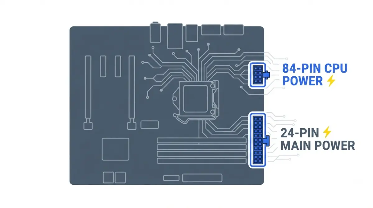
Table of Contents
Two plugs power your motherboard — here’s which is which
Your motherboard power connector setup comes down to two plugs. The wide 24-pin plug powers the board, and the square 8-pin EPS plug beside the CPU socket is the processor’s dedicated 12 V feed.
If you’re mid-build
Read the 24-pin section first, then the seating steps. If two 8-pin plugs in your cable bundle look identical, read the CPU-versus-PCIe section before plugging in either one.
If a CPU power socket is still empty
Many current boards have two CPU power sockets, and your exact board’s manual decides whether the second must be filled. If the PC won’t power on at all, skip to the troubleshooting order near the end.
ℹ️ Risk Note: Use only the power cables supplied with your exact power supply model, or replacements its manufacturer lists for it, because a plug that fits can still be wired differently. If any connector looks scorched or melted, or you smell burning, switch off at the wall and contact the PSU manufacturer’s support before powering on again.
What the 24-pin connector actually powers
The 24-pin main power connector feeds the motherboard itself, while the CPU gets its own separate 12 V connector.
The rails inside the 24 pins
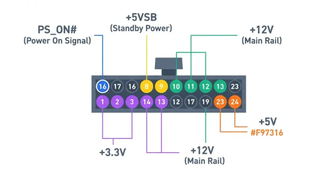
The board pulls a signal called PS_ON# low to switch the power supply on. Intel’s design guide says that turns on the PSU’s four main rails: +12 V, +5 V, +3.3 V and −12 V. The +5 V standby rail ignores that signal and stays live whenever the PSU has wall power.
| Signal or rail | What it does |
|---|---|
| PS_ON# | The motherboard’s on/off request to the power supply |
| +5VSB | Standby power, live whenever wall power is present |
| PWR_OK | Goes low if +12 V, +5 V or +3.3 V fall below threshold |
Source: Intel ATX Version 3 Multi Rail Desktop Platform Power Supply Design Guide, rev. 2.1a (November 2023).
🔍 Why It Works: Your case’s power button never switches mains power directly. It signals the motherboard, which pulls PS_ON# low. The standby rail, already live, is what keeps that circuit ready while the PC is off.
You can read the signal definition in Intel’s PS_ON# specification.
Why your cable splits into 20+4
PSU maker darkFlash notes that older boards used a 20-pin socket and newer ones use 24 pins. The extra four pins exist for backward compatibility. On a 24-pin board, both sections go in together as one plug.
One 8-pin or two? Your board’s manual decides
Only your exact board’s manual tells you whether a second CPU power socket must be filled. Intel’s design guide describes the board’s CPU power input as a single 8-pin connector, or one or two 4-pin connectors. Many current boards go beyond that baseline with a second 8-pin, and manufacturers word the rule differently.
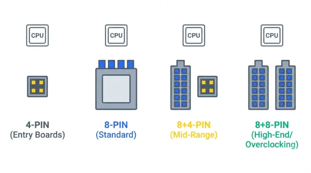
4-pin, 8-pin, 8+4 and 8+8 layouts
You’ll meet four layouts: a single 4-pin, a single 8-pin, an 8-pin plus a 4-pin, or two 8-pins. The socket count alone doesn’t tell you the rule, as three current manuals show.
CPU Power Socket Fill Matrix
| Board | Platform | CPU power sockets | Manual’s rule | Key Detail |
|---|---|---|---|---|
| ASUS TUF GAMING B850-PLUS WIFI | AM5 / B850 | 2 × 8-pin | One 8-pin, or both | One is supported |
| MSI MAG X870 TOMAHAWK WIFI | AM5 / X870 | 2 × 8-pin (CPU_PWR1–2) | All power cables securely connected | Also has an 8-pin PCIE_PWR1 socket |
| GIGABYTE Z890 AORUS ELITE X ICE | LGA1851 / Z890 | 2 × 2×4 (12V_2X4_1–2) | Won’t start without the 12V connector | One-or-both rule not stated |
Source: ASUS TUF GAMING B850-PLUS WIFI user manual (power connectors section) and tech specs; MSI MAG X870 TOMAHAWK WIFI user guide, p. 46; GIGABYTE Z890 AORUS ELITE X ICE user manual, p. 22. Manuals checked September 2026.
Here is how each manual phrases it:
- ASUS: the TUF GAMING B850-PLUS WIFI manual tells you to connect the 8-pin plug, or both 8-pin plugs.
- MSI: its guide asks that all power cables be securely connected for stable operation.
- GIGABYTE: its manual warns the computer won’t start without the 12V connector, but gives no one-or-both rule.
Reading the manual’s power section
Board makers label these sockets differently: MSI uses CPU_PWR1 and CPU_PWR2, and GIGABYTE uses 12V_2X4_1 and 12V_2X4_2. Find that label on the layout page, then read the note in the connector section.
🧩 Compatibility Check: Open your board manual’s power connector section and read the caution under the CPU sockets. “Or both” means one 8-pin is supported. “All power cables” means fill every socket. If the manual is silent, ask the board maker’s support before you rely on one cable.
ATX12V vs EPS12V in one line
Both names describe the 12 V CPU connector. Intel’s guide defines 4-pin and 8-pin versions, and a splittable 4+4 CPU cable fits either socket.
How much power an EPS 8-pin connector carries
An 8-pin EPS connector has four +12 V pins. Intel bases its connector guidance on 6–8 A per pin, which calculates to 288–384 W of connector capacity.
The pin-count math
| CPU connector | +12 V pins | Calculated capacity | Key Detail |
|---|---|---|---|
| 4-pin | 2 | 144–192 W | Two +12 V, two ground |
| 8-pin | 4 | 288–384 W | Four +12 V, four ground |
| 8-pin + 4-pin | 6 | 432–576 W | Combined sockets |
| 8-pin + 8-pin | 8 | 576–768 W | Combined sockets |
Source: pin counts from Intel ATX Version 3 design guide rev. 2.1a, Tables 5-8 and 5-9; 6–8 A per pin from the same guide’s modular connector section. Watts calculated by The Silicon Scroll (pins × amps × 12 V), not measured.
📊 Spec Check: In Intel’s +12 V power connector pinout, the 8-pin connector’s pins 1–4 are ground and pins 5–8 are +12 V, all on 18 AWG wire.
The math describes what the connector and wire can carry. It doesn’t tell you what your CPU draws.
Why online wattage figures disagree
Intel separates the current a PSU pin and 18 AWG wire can supply from what the connected component actually demands. You’ll see single figures quoted elsewhere, such as 336 W or 350 W per connector, without being told which side of that line they describe.
🧩 Compatibility Check: Compare the maximum power figure on your CPU’s official spec page with your board manual’s socket rule. The connector rating is only a ceiling; the manual still decides how many sockets you fill.
CPU 8-pin vs PCIe 8-pin: why they aren’t swappable
A CPU (EPS) cable and a PCIe cable can both end in an 8-pin plug, but they aren’t interchangeable in either direction.
How to tell the cables apart
| Feature | CPU (EPS) 8-pin | PCIe 8-pin |
|---|---|---|
| +12 V power pins | 4 | 3 |
| Goes to | CPU power socket on the motherboard | Graphics card, or a board socket labelled PCIe |
| Printed label (Corsair PSUs) | CPU | PCIe |
Source: Intel ATX Version 3 design guide rev. 2.1a (+12 V pinout; PCIe 2×4 connector uses three power and three ground pins); Corsair.
Corsair’s explanation of CPU vs PCIe cables says a PCIe cable doesn’t belong in the motherboard’s 8-pin CPU socket: the connector is physically different, the wiring differs, and it could damage your components. Corsair also marks each connector CPU or PCIe, so match the printed label rather than the shape. For the graphics card side of the build, see our graphics card fit checks.
⚠️ Watch Out: Some boards carry an 8-pin socket that takes a PCIe cable, not a CPU cable. Corsair explains that MSI’s MAG X870 TOMAHAWK WIFI has a supplemental PCIe power connector providing up to 420 W, labelled PCIE_PWR1 in MSI’s manual. Match every socket label in your manual to the cable’s printed label.
Modular cables stay with their own PSU
Use only the cables that came with your power supply, or replacements its manufacturer lists for that exact model. ASUS support recommends the PSU’s original power cables and advises against extension cables or adapters.
✅ Do This: Lost or damaged a modular cable? Contact your PSU manufacturer’s support with the exact model number and ask for its official replacement. Don’t buy a third-party cable that only looks compatible.
Plugging in the 24-pin and EPS cables so they fully seat
Both power plugs go in the same way: one orientation, firm pressure, fully inserted.
- Switch the power supply off first. GIGABYTE’s manual says to make sure the power supply is off and all devices are properly installed before you connect power.
- Line up the latch with the socket’s catch. ASUS notes the plugs are designed to fit in only one orientation, so never force one.
- Push down firmly until the plug is fully inserted. Press on the connector body, not the wires.
- Check that each plug sits flat, with no edge raised above the socket.
Joining 4+4 and 20+4 before you plug in
On an 8-pin CPU socket, clip both halves of a 4+4 cable together first. Corsair notes the CPU cable splits only for boards with room for a 4-pin connector. Treat a 20+4 cable the same way on a 24-pin socket.
If you’re fitting a large air cooler, confirm you can still reach the CPU power socket once it’s mounted. Our CPU cooler socket compatibility and clearance guide covers the fit checks.
Boards without a 24-pin: ATX12VO
Intel’s ATX12VO connector specification uses a 10-pin main board connector. When a board needs more, an extra board power connector can add 216–288 W. Check your board’s spec page for its main power connector before buying a power supply.
PC won’t power on? Check the power plugs in this order
Before suspecting a failed part, rule out a no-power problem at the plugs, in this order.
No fans, no lights
- Check the PSU’s rear switch is on and its wall cable is seated.
- Check the 24-pin plug is fully latched, with both halves in.
- Check the case power-button lead is on the header pins your manual names.
Fans spin, no display, CPU LED lit
- Check the EPS plug is latched, and that it’s a CPU cable, not PCIe.
- Check the second CPU socket is filled if your manual requires it.
- Read the board’s status LEDs. ASUS tells owners of selected boards to check the Q-LEDs at power-on, and your manual’s LED table names the stage where the board stopped.
If power is ruled out, confirm your board’s BIOS supports the CPU.
⚠️ Watch Out: A scorched, discoloured or melted connector means stop. Switch off at the wall, leave the cable unplugged, and contact the PSU or motherboard manufacturer’s support before powering on again.
Frequently asked questions
1. Do I need both the 24-pin and the 8-pin CPU cable?
Yes. The 24-pin powers the board and the 8-pin CPU cable feeds the processor; GIGABYTE warns a board won’t start without it.
2. Do I need to plug in both 8-pin CPU connectors?
Only if your board’s manual requires it. ASUS’s TUF B850-PLUS allows one or both; MSI’s X870 Tomahawk asks for every power cable.
3. Can I use a PCIe 8-pin cable for CPU power?
No. Corsair says a PCIe cable and the 8-pin CPU plug are physically different and wired differently, so swapping them can damage components.
4. What is a 4+4 pin CPU connector?
A 4+4 pin CPU cable splits in two so it fits a 4-pin socket. Clip both halves together for an 8-pin socket.
5. What’s the difference between ATX12V and EPS12V?
Both name the 12 V CPU connector. Intel’s guide defines 4-pin and 8-pin versions, and board labels vary by manufacturer.
6. How many watts does an 8-pin EPS connector carry?
Four +12 V pins at Intel’s 6–8 A per pin calculates to 288–384 W of connector capacity, not CPU draw.
7. Why does my motherboard have two CPU power sockets?
A second socket adds 12 V pins for the CPU. Your motherboard manual’s power section says whether filling it is required.
8. What is a 20+4 pin connector for?
A 20+4 pin cable fits older 20-pin boards. darkFlash notes the extra four pins keep it compatible with 24-pin sockets.
9. Can I use modular cables from a different PSU?
Use only cables made for your exact PSU model; ASUS support advises the original PSU cables, not extensions or adapters. Contact your PSU manufacturer for official replacements.
10. Why won’t my PC turn on after connecting power cables?
Check the PSU switch, both 24-pin halves, the EPS latch, the cable type, and whether your manual requires a second CPU socket.
What to do next
Before you close the case, open your motherboard manual’s power section and confirm how many CPU sockets it wants filled. Check that every cable’s printed label matches its socket. Then work through the five-check motherboard compatibility order, and if you’re still choosing a processor, check CPU and motherboard compatibility before you order. This guide draws on manufacturer manuals and Intel’s design guides, and we did not physically test these parts.