Motherboard Front Panel Header Wiring, Step-by-Step
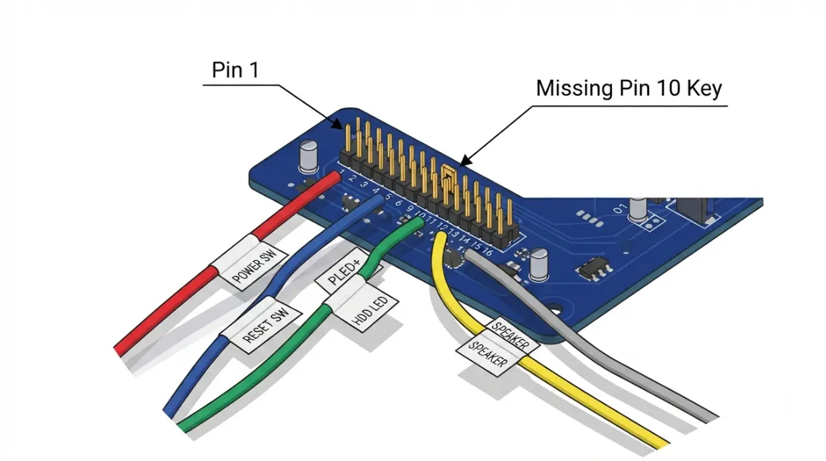
Table of Contents
Where the front panel wires go on your motherboard
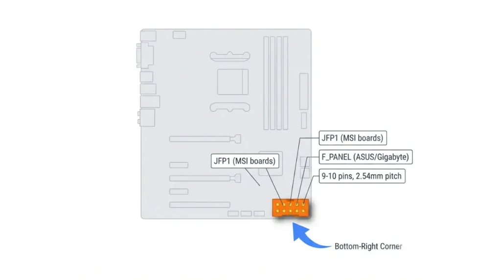
Front panel header wiring on a motherboard comes down to one small front panel header, where your case’s power button, reset button and status lights plug in. Nothing on it carries mains voltage.
- First build? Read the sections below in order.
- Pins don’t match a diagram you found? Jump to the brand layout table.
- PC won’t turn on? Go straight to troubleshooting.
The four leads every case has
Most cases supply a power switch lead, a reset switch lead, a power LED lead and an HDD LED lead. Some add a speaker or chassis intrusion lead.
Find the header and its manual page first
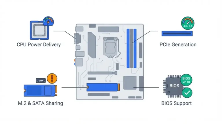
On current boards, look for a pin block labeled JFP1 (MSI) or F_PANEL (ASUS and Gigabyte). Then open your manual’s connector section, because that diagram is the only one guaranteed to match your exact board. It’s one of the checks in our motherboard compatibility guide.
What each front panel pin actually does
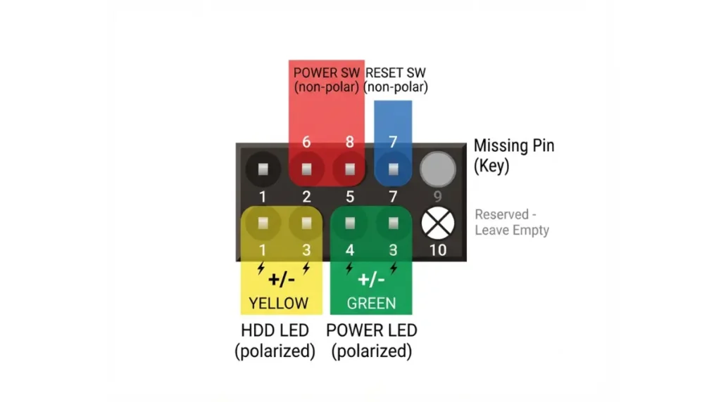
Polarity matters only for the LEDs and the speaker. The power and reset switches work either way round. This is MSI’s current 10-pin layout:
| Pins | Lead | Polarity matters? |
|---|---|---|
| 1 (+), 3 (−) | HDD LED | Yes |
| 2 (+), 4 (−) | Power LED | Yes |
| 5, 7 | Reset switch | No |
| 6, 8 | Power switch | No |
| 9 | Reserved: leave empty | — |
| 10 | No pin (key) | — |
Source: MSI MAG X870 Tomahawk WiFi user guide (JFP1 diagram) and MSI MPG Z490 Gaming Plus user guide (JFP1 pin table).
Power and reset are momentary switches
🔍 Why It Works: Pressing the button briefly connects its two pins, and the board only detects that connection. The direction of the plug makes no difference.
The LEDs are polarized
An LED lights only when current flows through it one way, so + must meet +. The LEDs are indicators only, and the PC powers on without them.
Pin 9 is reserved, pin 10 is the key
Some pinout pages online call pin 9 the missing pin. MSI’s JFP1 diagram shows pin 9 as reserved and pin 10 as absent. That matches the switch/LED header in Intel’s Front Panel I/O Connectivity Design Guide.
Why the pin layout changes between ASUS, MSI and Gigabyte
Current boards from these three brands use two header sizes, and only MSI’s matches the 10-pin table above exactly.
| Brand / header | Size | Power LED | Extras on header | Key Detail |
|---|---|---|---|---|
| MSI JFP1 (MAG X870 Tomahawk WiFi) | 10-pin, Intel layout | 2-pin | None (speaker on JFP2) | Pin 9 reserved, pin 10 absent |
| ASUS F_PANEL (TUF Gaming B850-Plus WiFi) | 10-1 pin | 2-pin +PWR_LED− | None (chassis intrusion is a separate header) | Power LED blinks in sleep |
| Gigabyte F_PANEL (X870 Gaming X WiFi7) | 20-pin | 2-pin PLED, plus a PWR_LED position | Speaker, chassis intrusion | Power LED off in sleep or shutdown |
Source: MSI MAG X870 Tomahawk WiFi user guide; ASUS TUF Gaming B850-Plus WiFi user manual (Revised Edition V2, January 2025); Gigabyte X870 Gaming X WiFi7 user’s manual (Rev. 1001). All three are current AM5 boards.
MSI JFP1: the Intel 10-pin layout
MSI keeps JFP1 for switches and LEDs only. The speaker and buzzer go on a separate JFP2 header.
Gigabyte F_PANEL: 20 pins with CI and two power LED spots
Gigabyte’s F_PANEL pin assignment adds speaker and chassis intrusion pins. It also offers two places for the power LED. The manual tells builders to note positive and negative pins before connecting.
ASUS F_PANEL: 10-1 pin on current boards
ASUS’s front panel system header carries the power LED, storage activity LED, power button and reset pins. Chassis intrusion connects to its own header elsewhere on the board.
🧩 Compatibility Check: Layouts differ between models and generations from the same brand, and older boards often used larger blocks. Match your leads to the diagram in your own board’s manual, not to this table.
How to connect front panel cables step by step
Work with your manual open to the front panel header diagram.
Before you start
- Switch off the power supply and unplug the power cord. The ASUS and Gigabyte manuals both require this before connecting cables.
- Find pin 1 on the header using the manual. On Intel-layout boards, the empty pin 10 position is a second landmark.
Plug order that avoids a one-pin offset
- Fit the power switch lead onto the pins your manual shows.
- Add the reset switch lead.
- Fit the power LED and HDD LED leads, matching + to +.
- Check that no plug sits one pin over.
- Secure the cables with a tie wrap. Intel’s design guide recommends securing front panel cables so they can’t work loose.
Using a Q-Connector or similar adapter
Some boards ship an adapter block. You wire the leads to it outside the case, then press it onto the header in one piece. Gigabyte’s X870 Gaming X WiFi7 box lists a G Connector, while the ASUS TUF Gaming B850-Plus WiFi package list includes no adapter.
Which way round do the LED plugs go?
If an LED plug is backwards, the LED stays dark. Flip it and it will work.
Reading + and − on the board
Current manuals mark polarity in the pin names. ASUS labels its pins +PWR_LED− and +HDD_LED−, and MSI and Gigabyte mark + and − on their diagrams.
Matching the plug
Many case plugs carry a small + or − on the housing or label. Line that mark up with the matching pin in your manual’s diagram.
What happens if it’s backwards
Lenovo notes that a reversed system panel connection won’t damage the motherboard. The LED simply stays off until you reverse it.
⚠️ Watch Out: Some guides say the printed text on the plug always faces down. That’s a habit, not a standard, so go by the + marks instead.
Speaker, chassis intrusion and 3-pin power LED leads
Leftover leads are usually optional, and whether they have a home depends on the board.
Speaker and buzzer headers
A case speaker only reports startup beep codes. Gigabyte notes that one short beep means no problem was detected. MSI uses a separate JFP2 header for it, Gigabyte includes speaker pins on F_PANEL, and the ASUS TUF Gaming B850-Plus WiFi’s front panel header has none.
Chassis intrusion
This lead detects when the side panel comes off, and it works only if your case has an intrusion switch or sensor. Gigabyte puts it on F_PANEL, while ASUS uses a separate header.
Power LED behavior differs by brand
On the Gigabyte X870 Gaming X WiFi7, the power LED turns off in sleep. On the ASUS TUF Gaming B850-Plus WiFi, it blinks in sleep, so either behavior can be normal. If your case’s power LED plug doesn’t fit a 2-pin spot, check your manual for a second power LED position, like Gigabyte’s PWR_LED.
PC won’t turn on after wiring the front panel?
A dead power button after a build is common, and the cause is usually a plug in the wrong spot.
Check for a one-pin offset
Compare every plug against the manual diagram, counting from pin 1.
Rule out the case button
Some boards, like Gigabyte’s X870 Gaming X WiFi7, have onboard power and reset buttons for open-case testing, so press those first. Otherwise, move the reset lead onto the power switch pins and press reset. If the PC starts, the case power button or its lead is at fault, so put the leads back afterward.
Fans spin but no display: look elsewhere
Once the fans spin, the front panel has done its job. Check the board’s debug LEDs (Q-LEDs on ASUS, status LEDs on Gigabyte), then read about RAM compatibility issues that stop POST. If there’s no sign of power at all, confirm the 24-pin and EPS power connectors are fully seated.
✅ Do This: If a header pin is bent, don’t force a plug onto it. Contact your board maker’s support or an authorized service center before attempting a fix.
Front panel header FAQ
1. Which pins are the power switch pins?
On Intel-layout front panel headers, such as MSI’s JFP1, the power switch uses pins 6 and 8. Check your manual’s diagram.
2. Does it matter which way the power switch plug goes?
No. Front panel power and reset switches only bridge two pins, so either orientation works.
3. What happens if a front panel LED is plugged in backwards?
The front panel LED stays dark. A reversed connection won’t damage the motherboard, so just flip the plug.
4. Why is one pin missing on the front panel header?
On Intel-layout front panel headers, pin 10 is left out as a key. Pin 9 is reserved and should stay empty.
5. What is JFP1?
JFP1 is MSI’s front panel header name. It uses the 10-pin switch/LED layout from Intel’s Front Panel I/O Connectivity Design Guide.
6. What is F_PANEL?
F_PANEL is the front panel header label on current ASUS and Gigabyte boards. Gigabyte’s is 20-pin, and ASUS’s TUF B850-Plus WiFi uses 10-1 pin.
7. Do I need to connect the case speaker?
No. A front panel speaker only reports startup beep codes. MSI boards use a separate JFP2 header for it.
8. What is a chassis intrusion header?
It detects side panel removal, working alongside the front panel header. It only works if your case has an intrusion switch or sensor.
9. Why won’t my PC turn on after connecting the front panel?
Check that the front panel power switch lead isn’t one pin off. Then test with the board’s onboard power button or the reset lead.
10. Do I need to connect the HDD LED?
No. The front panel HDD LED is an indicator only, and the PC powers on without it connected.
Wire it once, check it against your manual
Switches go either way, LEDs need + to +, and header layouts differ by brand and model. Once the PC powers on, confirm whether your BIOS supports your CPU, or return to the full motherboard compatibility checklist. Every pin assignment here comes from a manufacturer manual, and we didn’t physically test any hardware.